A Complete Visual and Technical Guide to Identifying GFCI Circuit Breakers — Physical Features, Panel Labels, Functionality, and How They Compare to Standard Breakers
Opening an electrical panel for the first time can be confusing — rows of identical-looking switches, each protecting a different circuit. But one type of circuit breaker stands out from the rest with a set of distinctive visual features that make it immediately recognisable once you know what to look for. That device is the GFCI (Ground Fault Circuit Interrupter) circuit breaker.
Whether you are checking whether your bathroom or kitchen circuits already have GFCI protection, identifying a tripped GFCI breaker, shopping for a replacement, or simply trying to understand your electrical panel, this guide covers everything about what a GFCI circuit breaker looks like — from its physical housing and distinctive buttons to the markings on its face, the wiring that sets it apart inside the panel, and how its appearance differs from standard breakers and from GFCI outlets. Understanding these visual cues gives you the confidence to identify, test, and assess GFCI protection in any panel.
Quick Answer: What Does a GFCI Breaker Look Like?
A GFCI circuit breaker looks similar to a standard circuit breaker at first glance — same rectangular plastic housing, same toggle switch, same overall size — but it has two features that immediately distinguish it from any other breaker in the panel:
1. The TEST Button
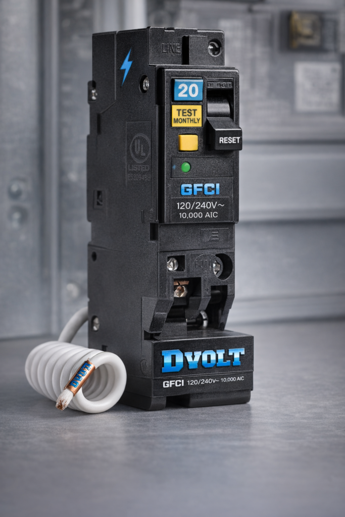
Every GFCI breaker has a small rectangular or oval button on its face labelled TEST. This button is not present on standard circuit breakers. When pressed, it simulates a ground fault and should immediately trip the breaker — cutting power to the circuit. It is typically white or yellow in colour and sits alongside the toggle switch on the breaker face.
2. The RESET Button (or Toggle Position)
Some GFCI breakers have a separate RESET button adjacent to the TEST button. On others, resetting is accomplished by moving the toggle fully to OFF then back to ON. Either way, the presence of a TEST button is the single most reliable visual identifier of a GFCI breaker in any panel.
One-Line Identification: If you see a circuit breaker with a small button labelled TEST on its face — that is a GFCI breaker (or an AFCI/GFCI combination breaker). No standard circuit breaker has a TEST button. This single feature is the fastest and most reliable way to identify GFCI protection in any panel.
Physical Features in Detail
Beyond the TEST button, a GFCI circuit breaker has several additional physical characteristics that distinguish it from standard breakers when examined closely:
Housing and Body
GFCI breakers are housed in compact, impact-resistant thermoplastic enclosures — the same durable material used for standard breakers. The body is typically slightly deeper front-to-back than a standard breaker of the same amperage, due to the additional electronic components inside. The overall width and height conform to the panel’s standard slot dimensions.
Toggle Switch
Like all circuit breakers, a GFCI breaker has a toggle handle that moves between ON, OFF, and TRIPPED positions. The toggle typically has a different colour or marking on the face to indicate its rated amperage and breaker type. The toggle on a GFCI breaker may be slightly narrower than on standard breakers to accommodate the TEST button on the same face.
TEST Button
The TEST button is typically rectangular or oval, approximately 8–12mm wide, and positioned on the face of the breaker adjacent to the toggle. It is usually white, yellow, or grey. Pressing it applies a small internal resistance that simulates a ground fault imbalance — triggering the GFCI trip mechanism without requiring an actual fault condition.
White Pigtail Wire
On the wiring side of the breaker, a GFCI unit has a factory-installed short white wire called a pigtail emerging from the breaker body. This wire connects to the panel’s neutral bus bar during installation. No standard breaker has this pigtail — its presence on an installed breaker is a definitive sign that the breaker is a GFCI (or AFCI/GFCI combination) type.
Neutral Terminal
A GFCI breaker has a second terminal in addition to the standard hot (line) terminal — the load neutral terminal. This terminal receives the white (neutral) wire from the protected circuit. Standard breakers have only one terminal. The presence of this second terminal on the breaker body is visible when the breaker is removed from the panel.
Colour Accents
Many manufacturers use colour coding to differentiate GFCI breakers from standard types. Common approaches include a yellow or white TEST button that contrasts with the darker breaker body, coloured indicator windows that show the trip status, or a distinct face colour on the breaker body itself. Colour conventions vary by manufacturer — refer to the brand-specific section below.
Face Markings and Labels
The printed markings on a GFCI circuit breaker’s face communicate everything needed to identify and specify the device. Here is what you will typically see:
| Marking / Label | Meaning | Example |
|---|---|---|
| TEST | Button that simulates a ground fault to verify GFCI function — present on every GFCI breaker | “TEST” in raised or printed lettering on or beside the button |
| RESET | Button to restore power after a GFCI trip — present on breakers with a separate reset button; others use the toggle handle | “RESET” label beside a separate push button |
| GFCI | Identifies the breaker type — may be printed on the face or on a label on the toggle | “GFCI” or “GFI” in moulded or printed text |
| Amperage rating | Maximum continuous current the breaker handles — printed on the toggle face | “15A”, “20A”, “30A” |
| Voltage rating | System voltage the breaker is designed for | “120/240V” or “120V” for single-pole residential GFCI breakers |
| Manufacturer name or logo | Identifies the brand — critical for panel compatibility verification | Square D, Eaton, Siemens, GE etc. |
| UL Listed mark | Confirms the breaker has been independently tested and listed to UL 943 (GFCI) and UL 489 (circuit breaker) standards | UL logo with listing number |
| Panel compatibility designation | The panel series the breaker is listed for — critical to verify before installation | “For use in QO panels” or “CH series” etc. |
Where to Find the Full Specification: The complete breaker specification — including exact model number, amperage, voltage, interrupting capacity, and listed panel compatibility — is printed on a label on the side of the breaker body. This label is visible when the breaker is removed from the panel slot and is the authoritative reference for all specification questions.
How a GFCI Breaker Looks Inside the Panel
When you open an electrical panel cover and look at the installed breakers, a GFCI breaker is identifiable by several visual cues even before reading any labels:
TEST Button Visible Through Panel Cover
The panel cover has openings aligned with each breaker’s toggle. For GFCI breakers, the opening is slightly larger or differently shaped to accommodate both the toggle and the TEST button, which protrudes through the panel cover face. Looking at the installed panel, any breaker position with a small button visible alongside the toggle is a GFCI (or AFCI/GFCI) breaker.
White Pigtail Routed to Neutral Bus Bar
With the panel cover removed, a GFCI breaker is immediately distinguishable by its white pigtail wire — a short white conductor emerging from the side of the breaker body and routed to the panel’s neutral bus bar. This pigtail is unique to GFCI and AFCI breakers; no standard circuit breaker has it.
Two Wires at the Breaker Position
At a standard breaker position, one wire connects to the breaker terminal (the hot black wire) and one wire runs to the neutral bus bar (the white neutral wire). At a GFCI breaker position, both the black wire and the white wire connect to the breaker itself — the white wire goes to the breaker’s neutral terminal rather than directly to the neutral bus bar. This two-wire connection at the breaker (plus the pigtail) is a visual distinguisher from standard breaker positions.
Slightly Greater Depth
GFCI breakers are often slightly deeper than standard breakers of the same amperage, due to the additional electronic components inside. This is generally not visible with the panel cover on, but is apparent when comparing breakers side by side or when fitting the panel cover — the cover’s front face may sit slightly further from the GFCI breaker’s toggle than from adjacent standard breakers.
GFCI Breaker vs. Standard Breaker — Visual Comparison
| Visual Feature | Standard Circuit Breaker | GFCI Circuit Breaker |
|---|---|---|
| TEST button on face | Not present | Present — the defining visual identifier |
| RESET button on face | Not present | Present on many models; others use toggle-only reset |
| Toggle handle | Full-width toggle across breaker face | Narrower toggle to share face space with TEST/RESET buttons |
| White pigtail wire (inside panel) | Not present | Present — routes to panel neutral bus bar |
| Number of terminals | One (hot/line terminal only) | Two — hot terminal + neutral (load neutral) terminal |
| Wiring at breaker position | Black wire to breaker; white wire to neutral bus bar | Black wire to breaker hot terminal; white wire to breaker neutral terminal; pigtail to neutral bus bar |
| Face label / text | Amperage and voltage ratings only | Amperage, voltage, “GFCI” or “GFI” designation, TEST/RESET labels |
| Body depth | Standard | Often slightly deeper due to internal electronics |
| Colour accents | Typically uniform dark grey or black | TEST button often white, yellow, or contrasting colour; some brands use a distinct face colour |
Appearance by Major Brand
While all GFCI breakers share the core visual characteristics described above, each major manufacturer has a distinctive appearance for their GFCI products:
| Brand | Panel Series | GFCI Breaker Appearance Notes |
|---|---|---|
| Square D (Schneider Electric) | QO series | Distinctive visi-trip indicator window on toggle; TEST button is white with “TEST” label; QO GFCI breakers have a characteristic “click-click” double positive engagement when installed; the QO series uses a gold-coloured bus stab |
| Square D (Schneider Electric) | Homeline series | Similar appearance to QO but without the visi-trip window; TEST button present on GFCI models; Homeline and QO breakers are NOT interchangeable despite similar appearance |
| Eaton / Cutler-Hammer | CH series | TEST button is typically white; CH GFCI breakers often have a yellow-coloured TEST button on some models; “GFCI” printed on the breaker face; the CH series uses a distinct brown or dark grey housing |
| Eaton / Cutler-Hammer | BR series | Similar visual layout to CH series; TEST button present; BR and CH series breakers have different bus stab configurations and are not interchangeable |
| Siemens / Murray | QP / MP-T series | TEST button is white; “GFCI” designation on face; Siemens GFCI breakers often have a white face accent panel distinguishing them from standard grey breakers; Siemens and Murray GFCI breakers are generally cross-compatible within compatible panel families |
| GE / General Electric | THQL series | TEST button present with white colouring; “GFCI” marked on face; GE GFCI breakers maintain the same overall form factor as standard THQL breakers but with the additional button and labelling |
AFCI, GFCI, and Dual-Function: How to Tell Them Apart Visually
With the increasing adoption of AFCI (Arc Fault Circuit Interrupter) breakers and dual-function AFCI/GFCI breakers, it is useful to know how to distinguish between all three types visually:
| Feature | Standard Breaker | GFCI Breaker | AFCI Breaker | AFCI/GFCI Combination |
|---|---|---|---|---|
| TEST button | None | Present — labelled “TEST” | Present — labelled “TEST” | Present — labelled “TEST” |
| Face designation label | None | “GFCI” or “GFI” | “AFCI” or “AFC” | “AFCI/GFCI” or “Dual Function” or “DF” |
| White pigtail wire | None | Present | Present | Present |
| Body colour accent | Uniform dark grey/black | Varies by brand — often white/yellow TEST button | Varies by brand — often yellow/orange TEST button on some models | Varies by brand — distinctive labelling across full face width |
| Protection provided | Overload and short circuit only | Overload, short circuit, and ground fault (4–6 mA) | Overload, short circuit, and arc fault | Overload, short circuit, ground fault, and arc fault |
When in Doubt — Read the Label: The face of every GFCI, AFCI, or combination breaker will be labelled with its type. If you see a TEST button but are not sure whether the breaker is GFCI, AFCI, or dual-function, look for the type designation printed on the breaker face or toggle. The label is the authoritative identifier — do not rely on colour alone, as colour conventions differ by manufacturer and product generation.
Identifying a Tripped GFCI Breaker
A GFCI breaker that has tripped due to a ground fault looks different from a breaker that has tripped due to an overload — and different again from a breaker in the normal ON or OFF positions. Knowing what a tripped GFCI looks like helps you identify the problem and reset it correctly:
Normal ON Position
Toggle is in the full ON position, aligned with other ON breakers. TEST button is in its normal protruding position — not depressed. The circuit is energised and the GFCI is actively monitoring.
Normal OFF Position
Toggle is in the full OFF position — moved to the opposite end from ON. This is a deliberate manual switch-off. The circuit is de-energised but the GFCI has not tripped. The TEST button remains in its normal position.
Tripped Position (GFCI or Overload)
On most GFCI breakers, a trip moves the toggle to a middle position — halfway between ON and OFF — or the toggle moves fully to OFF while a separate indicator changes state. On breakers with a visi-trip window (such as Square D QO), a red or orange indicator becomes visible in the window. The TEST button remains in its normal position when the breaker has tripped due to a ground fault.
How to Reset
To reset a tripped GFCI breaker: move the toggle fully to OFF first (this is essential — simply pushing from the middle tripped position to ON will not reset the mechanism on most designs), then move it fully to ON. If the breaker trips again immediately, a fault condition still exists in the circuit — disconnect all loads and identify the fault before attempting another reset.
Source Quality GFCI Circuit Breakers from DVOLT
Professional-grade GFCI, AFCI, and combination circuit breakers for every residential and commercial panel installation
Browse Circuit Breakers → Visit DVOLT HomepageHow the GFCI Breaker Works
The visual features of a GFCI breaker — the TEST button, the neutral terminal, the pigtail wire — are all expressions of the device’s internal operating principle. Understanding that principle clarifies why each visible feature exists:
The Differential Current Transformer
At the heart of every GFCI breaker is a toroidal (doughnut-shaped) differential current transformer through which both the hot and neutral conductors of the protected circuit pass. Under normal operating conditions, the current flowing out on the hot conductor equals the current returning on the neutral conductor — the magnetic fields from the two conductors cancel each other out and the transformer output is zero.
When a ground fault occurs — a person touching a live conductor, a wire contacting a wet surface, or insulation failure allowing current to reach ground — some of the current leaving on the hot conductor does not return on the neutral. Instead it takes an unintended path to ground through the fault. The currents in the two conductors no longer cancel — the differential transformer produces an output signal proportional to the imbalance.
The Trip Threshold: 4–6 Milliamperes
When the imbalance exceeds approximately 4–6 milliamperes (0.004–0.006 amperes), the GFCI’s electronic circuit triggers the trip mechanism. The contacts open in approximately 1/40th of a second (25 milliseconds) — fast enough to prevent a lethal shock even when a person is in the current path. This is why the neutral wire from the protected circuit must connect to the GFCI breaker’s terminal: it must pass through the differential transformer for the measurement to be possible. A neutral wire connected to the bus bar instead bypasses the transformer entirely and disables the GFCI function.
The TEST Button’s Function
The TEST button applies a small internal resistance between the hot and neutral conductors that creates a deliberate, controlled imbalance — simulating the signature of a real ground fault without requiring an actual fault condition. This allows the GFCI function to be verified at any time without risk to people or equipment. The NEC and manufacturers recommend monthly testing to confirm the GFCI mechanism remains active and functional.
Common Issues and Troubleshooting
| Observed Symptom | Likely Cause | Action |
|---|---|---|
| Cannot find the GFCI breaker in the panel — all breakers look the same | GFCI protection may be at the outlet level (GFCI outlets) rather than the panel; or the panel cover openings may not clearly show the TEST button | Look for a small button alongside the toggle on each breaker face; if all breakers look identical with no buttons visible, GFCI protection for those circuits may be provided by GFCI outlets rather than breakers |
| GFCI breaker is in the middle (tripped) position — circuit has no power | Ground fault tripped the breaker, or a TEST was performed without resetting | Move toggle fully to OFF, then to ON; if it trips again immediately, a fault persists — unplug all circuit loads and retry; if it holds with nothing connected, reconnect one device at a time to identify the fault source |
| TEST button pressed — nothing happens, circuit stays on | GFCI function not operating — most likely the neutral wire is connected to the bus bar instead of the breaker neutral terminal; or the breaker is defective | Turn off main breaker and check neutral wire connection — the white circuit wire must be in the breaker’s neutral terminal; if correctly wired and TEST still does not trip, replace the breaker |
| New GFCI breaker trips immediately when switched ON | Neutral wire incorrectly connected to bus bar instead of breaker neutral terminal; or genuine ground fault on the circuit | Turn off main breaker; verify neutral wire routing; disconnect all circuit devices and retry — if breaker holds with nothing connected, fault is in a device |
| Cannot tell if a breaker is GFCI or AFCI from looking at the panel cover | Panel cover opening may show the toggle but obscure the type label | Turn off the main breaker and remove the panel cover; read the full face label on the breaker; GFCI breakers are labelled “GFCI” or “GFI”; AFCI breakers are labelled “AFCI” or “AFC”; dual-function breakers are labelled “AFCI/GFCI” or “DF” |
| GFCI breaker trips randomly with no obvious fault | An appliance on the circuit has minor insulation leakage that the GFCI detects; moisture in an outdoor outlet box; long circuit run creating capacitive leakage | Disconnect devices one at a time to identify the source; inspect outdoor boxes for moisture ingress; if nuisance tripping continues with all devices disconnected, the fault is in the circuit wiring — call a licensed electrician |
Frequently Asked Questions
Q1. What is the most obvious visual sign that a circuit breaker is a GFCI type?
The TEST button. Every GFCI circuit breaker has a small button labelled TEST on its face — this button is absent on all standard circuit breakers. If you see a TEST button on a breaker in your panel, that breaker is either a GFCI, AFCI, or dual-function AFCI/GFCI type. The type designation (GFCI, AFCI, or both) is printed on the breaker face alongside the amperage and voltage ratings.
Q2. How is a GFCI circuit breaker different in appearance from a GFCI outlet?
A GFCI circuit breaker is installed in the electrical panel, is the same size as a standard circuit breaker, and has a toggle handle plus a TEST button on its face. A GFCI outlet is installed in the wall at an outlet location, has the standard rectangular outlet shape with two or three receptacle slots, and also has TEST and RESET buttons — but they are located on the outlet face between the receptacle slots, not on a panel-mounted breaker. Both provide ground fault protection, but the breaker protects the entire circuit while the outlet protects that outlet and any outlets wired downstream of it.
Q3. Does a GFCI breaker look the same as a standard breaker in the panel?
At a glance, yes — same size, same housing material, same toggle. But on closer inspection several differences are visible: the TEST button on the face, the “GFCI” label, the white pigtail wire emerging from the side of the breaker body and routed to the neutral bus bar, and the fact that both the black and white circuit wires connect to the breaker itself rather than only the black wire. These differences are immediately apparent once the panel cover is removed.
Q4. What do the TEST and RESET buttons actually do?
The TEST button simulates a ground fault by applying a small internal resistance that creates a deliberate current imbalance. This causes the GFCI mechanism to trip — cutting power to the circuit — confirming that the protection is functioning correctly. The RESET button (or the toggle moved OFF then ON) re-engages the internal contacts after a trip, restoring power. Testing monthly with the TEST button is recommended to confirm the GFCI mechanism remains active and functional.
Q5. Why does a GFCI breaker have a white pigtail wire that a standard breaker does not?
The GFCI breaker’s differential current transformer must monitor both the hot and neutral conductors of the protected circuit simultaneously. The pigtail wire connects the breaker’s internal neutral reference circuit to the panel’s neutral bus bar — providing the ground-referenced neutral path that allows the differential transformer to make its comparison. Without this connection (and without the circuit neutral wire connecting to the breaker’s neutral terminal), the GFCI sensing circuit has no reference and cannot detect ground faults.
Q6. How do I tell the difference between a GFCI and an AFCI breaker visually?
Both types have a TEST button and a white pigtail wire — these features alone do not distinguish them. The distinction is on the face label: a GFCI breaker will be labelled “GFCI” or “GFI”; an AFCI breaker will be labelled “AFCI” or “AFC”; a dual-function combination breaker will be labelled “AFCI/GFCI” or “Dual Function.” If the panel cover obscures the label, turn off the main breaker and remove the cover to read the full face markings.
Q7. What position is a GFCI breaker in when it has tripped?
On most residential GFCI breakers, a trip moves the toggle to a middle position — halfway between ON and OFF. This is different from the full OFF position reached by a manual switch-off. Some breakers move fully to OFF when tripped, with a separate visual indicator (such as a coloured window) showing the tripped state. To reset, always move the toggle fully to OFF first, then back to ON — simply moving from the middle tripped position to ON will not reset the GFCI mechanism on most designs.
Q8. Can a GFCI breaker be used in any electrical panel?
No. A GFCI breaker must be explicitly listed as compatible with the specific panel brand and model in which it will be installed. GFCI breakers from one manufacturer are not interchangeable with panels from another, even if they appear identical and physically fit. Using a non-listed breaker voids the panel’s safety listing and creates a potentially unsafe installation. Always verify the breaker’s listed panel compatibility before purchase.
Q9. Is a GFCI breaker larger than a standard breaker?
In width and height, no — a single-pole GFCI breaker occupies the same panel slot as a standard single-pole breaker. The body depth may be slightly greater due to additional internal electronics, but this does not affect installation in a compatible panel. The slightly deeper profile may be noticeable when comparing a GFCI breaker side by side with a standard breaker of the same amperage, but it does not require any modification to the panel.
Q10. How often should a GFCI breaker be tested using the TEST button?
The NEC and most manufacturers recommend monthly testing. Press the TEST button — the breaker should trip and the circuit should lose power. Then reset by moving the toggle fully to OFF, then back to ON. Monthly testing confirms that the GFCI mechanism remains active and functional. GFCI devices can fail in a mode that leaves the circuit energised while the protective function is no longer operating — a failure that monthly testing will reveal before it creates a hazard.
Conclusion
A GFCI circuit breaker is designed to be visually distinctive — and once you know what to look for, it is immediately recognisable in any panel. The TEST button is the defining feature: no standard circuit breaker has one. The GFCI designation label, the white pigtail wire inside the panel, and the neutral terminal on the breaker body all reinforce the identification. Understanding these visual cues allows you to quickly confirm whether a circuit has GFCI protection, identify a tripped GFCI breaker, and select the correct replacement unit when one is needed.
Final Recommendations:
- Look for the TEST button — it is the single most reliable visual identifier of a GFCI breaker in any panel
- Confirm the type from the face label: “GFCI” for ground fault protection, “AFCI” for arc fault, “AFCI/GFCI” for dual-function
- Inside the panel, the white pigtail wire routed to the neutral bus bar is a definitive sign of a GFCI or AFCI breaker
- The circuit’s white neutral wire should connect to the breaker’s neutral terminal — not the bus bar — for the GFCI function to operate
- Never rely on physical appearance alone to confirm panel compatibility — always verify the breaker is listed for your specific panel model
- Test your GFCI breakers monthly using the TEST button to confirm the protection is active
- If a GFCI breaker trips and will not reset, or if the TEST button does not trip the breaker, consult a licensed electrician
Trust DVOLT for Quality Circuit Breakers
Professional-grade GFCI, AFCI, combination, and standard circuit breakers for every residential and commercial panel installation
Electrical safety is no accident—it’s the result of proper planning, quality components, and professional installation. DVOLT Electric—your partner in electrical safety.