A Complete Guide to AC Unit Contactor Testing — Signs of Failure, Tools Required, Step-by-Step Multimeter Tests, Results Interpretation, and When to Replace
The contactor is one of the hardest-working components in an air conditioning system. Every time your thermostat calls for cooling, the contactor closes its contacts to send high-voltage power to the compressor and condenser fan motor — and every time the setpoint is reached, it opens again to cut that power. Over a typical cooling season this cycle occurs hundreds or thousands of times, and over years of service the contactor’s contacts pit and erode, the coil ages, and the mechanical mechanism wears.
When the contactor begins to fail, it rarely does so dramatically — it degrades gradually, causing intermittent problems that are easy to misattribute to other AC components. Knowing how to test the contactor with a multimeter allows you to identify contact and coil failures quickly and accurately — avoiding costly misdiagnosis, unnecessary part replacement, and extended system downtime. This guide covers every aspect of AC contactor testing: the warning signs, the tools, the test procedures, how to interpret results, and when replacement is the right call.
Safety Note: Testing an AC contactor involves working with high-voltage electrical components. Always follow all safety precautions described in this guide. If you are unfamiliar with electrical testing or uncomfortable at any stage, contact a qualified HVAC technician.
What Is an AC Contactor and What Does It Do?
An AC contactor is an electrically operated switch that controls the flow of high-voltage power (typically 240V) to the compressor and condenser fan motor in an air conditioning unit. It is the interface between the low-voltage thermostat control circuit (24V) and the high-voltage power circuit that actually runs the compressor.
The Control Coil
When the thermostat calls for cooling, it sends 24V to the contactor’s control coil. The coil energises, creating an electromagnetic field that pulls the contactor’s armature down — closing the main contacts. When the setpoint is reached, the 24V signal stops, the coil de-energises, and a return spring opens the contacts.
The Main Contacts
The main contacts are the high-current switching points that connect the 240V supply to the compressor and condenser fan motor. They must make and break this heavy current reliably every cooling cycle. Over time, arc erosion causes pitting and carbon buildup on the contact surfaces — increasing resistance and eventually preventing reliable operation.
Typical Specifications
Residential AC contactors are typically rated at 24V AC control coil voltage, 240V AC main circuit voltage, and 25A–40A continuous current capacity. They are generally 2-pole (two sets of main contacts) for single-phase compressor circuits, though some larger systems use 3-pole units.
Location in the Unit
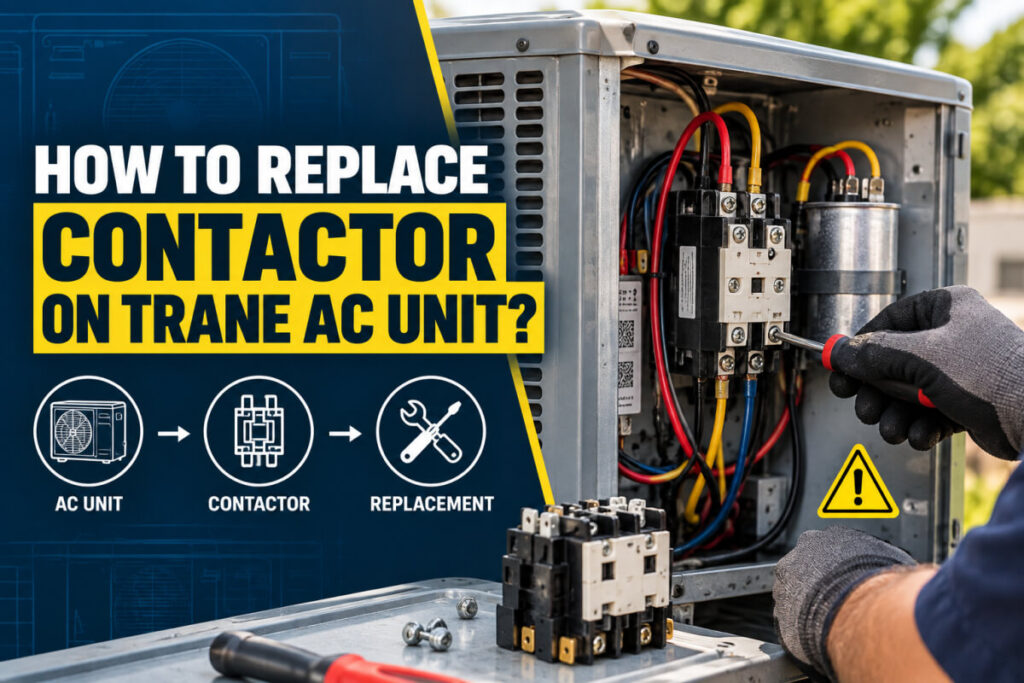
The contactor is located in the outdoor condensing unit — the large box outside the building. It is mounted inside the electrical access panel on the side of the unit, typically visible immediately upon removing the access panel cover. It is a rectangular component with wires connecting to it from both the high-voltage supply and the thermostat control cable.
Warning Signs of a Faulty AC Contactor
Contactor failures produce recognisable patterns of symptoms. Identifying these early allows testing and replacement before the contactor fails completely — often at the worst possible time during peak cooling demand:
| Symptom | What It Indicates | Urgency |
|---|---|---|
| AC does not turn on despite thermostat calling for cooling | Contactor contacts not closing, open coil, or no 24V control signal reaching the coil | 🔴 Urgent — system not functioning |
| Compressor runs continuously and will not shut off | Contacts welded closed — contactor cannot open even when coil is de-energised | 🔴 Urgent — compressor damage risk |
| Chattering or buzzing noise from the outdoor unit | Contactor coil receiving insufficient voltage to hold armature fully closed; contacts chattering open and closed | 🟠 High — investigate promptly |
| Intermittent operation — AC starts then stops randomly | Pitted contacts creating intermittent high-resistance connections; coil on the edge of failure | 🟠 High — diagnose before complete failure |
| Inconsistent cooling — system runs but output is reduced | Worn contacts with high resistance causing voltage drop at the compressor | 🟡 Moderate — test and assess |
| Visible burning, pitting, or carbon on contacts | Advanced contact erosion — replacement required regardless of electrical test results | 🔴 Replace immediately |
| Flickering indoor lights when AC cycles on | Excessive inrush current from a struggling compressor, or slow contact closure causing sustained arc | 🟡 Moderate — investigate contactor and compressor |
Tools and Equipment Required
Testing Equipment
- Digital multimeter — capable of measuring AC voltage (up to 600V), DC voltage, resistance (ohms), and continuity; a meter with a CAT III or CAT IV safety rating is recommended for work near high-voltage AC equipment
- Non-contact voltage tester — for confirming that power is off before touching any component; do not rely on the disconnect switch alone
- Clamp meter (optional) — for measuring the actual current draw of the compressor and fan motor while the system is running, which can indicate contact resistance issues
Hand Tools
- Flathead and Phillips screwdrivers — for removing the outdoor unit’s access panel
- Nut driver or socket set — some access panels use hex-head fasteners
- Needle-nose pliers — for carefully moving wires to access terminals without disconnecting them
Safety Equipment
- Insulated rubber gloves (Class 00 minimum) — rated for the voltages present in the AC unit
- Safety glasses or goggles — protection against arc flash and debris
- Non-conductive footwear — insulation from ground potential
Safety Precautions Before Testing
Safety Procedure Before Opening the Access Panel
- Turn off the thermostat to ensure the AC system is not calling for operation
- Open the outdoor disconnect box (usually mounted on the wall near the outdoor unit) and pull the disconnect block or switch it to OFF — this isolates the 240V supply to the outdoor unit
- Turn off the circuit breaker for the AC unit at the main electrical panel as a secondary isolation measure
- Wait at least 5 minutes after shutting down — capacitors in the unit store high-voltage charge that can be lethal if discharged through a person; allow time for residual charge to dissipate
- Verify de-energisation with a non-contact voltage tester before removing the access panel or touching any component — test at the disconnect and at the contactor terminals once the panel is open
- Put on insulated gloves and safety glasses before opening the access panel and throughout the testing process
Step 1: Visual Inspection
Before connecting any test equipment, a thorough visual inspection of the contactor can identify problems that multimeter testing alone may not reveal — and can save testing time by identifying obvious failures immediately:
-
Remove the Outdoor Unit Access Panel
With power confirmed off and gloves on, remove the screws securing the access panel on the side of the outdoor unit. Carefully lift the panel away and set it aside. The contactor will be visible as a rectangular component with multiple wire connections — typically located near the top of the electrical compartment.
-
Inspect the Contact Surfaces
Look closely at the contact tips visible at the front of the contactor. Healthy contacts are relatively smooth and silver-grey in colour. Worn contacts show: pitting (small craters in the contact surface from arc erosion), carbon deposits (black powdery or glazed residue), burning or scorching marks on the contact face or surrounding plastic, and in severe cases, melted or fused contact material.
Visibly Burned or Pitted Contacts Mean Replacement — Not Testing: If the contact surfaces show significant pitting, carbon buildup, or burning, the contactor has reached the end of its serviceable life. Electrical testing at this point is informational only — replacement is required regardless of what the multimeter shows. A contactor with severely eroded contacts may pass basic continuity tests while still having too-high contact resistance to operate reliably under load. -
Inspect Wiring and Connections
Examine all wires connected to the contactor terminals. Look for: melted or discoloured wire insulation near the terminals, loose or corroded terminal screws, wires that pull free easily (indicating a failed crimp or loose connection), and signs of heat damage to the surrounding components or wiring harness.
-
Inspect the Contactor Body
Check the contactor housing itself for: cracks or broken plastic, deformed or melted areas indicating previous arcing, the armature moving freely without binding when gently pressed (with power off), and any signs that previous arcing has escaped the contact chamber.
Passed Visual Inspection: Contacts are clean with minimal pitting; no burning or discolouration on contacts, wiring, or housing; all terminal connections are secure; armature moves freely. Proceed to electrical testing.
Step 2: Voltage Test (With Power On)
The voltage test confirms that the contactor is receiving both the 240V supply voltage and the 24V control signal correctly when the system is calling for cooling. This test is performed with the power on — exercise full caution.
-
Restore Power and Start the System
Re-insert the outdoor disconnect block or switch it to ON, and turn the AC circuit breaker back on. Set the thermostat to cooling mode with a setpoint well below the current room temperature — this ensures the system is calling for the compressor to run throughout the voltage test.
-
Test the Line-Side (Input) Voltage
Set the multimeter to AC voltage, range 300V or higher. Place the probes on the LINE terminals of the contactor — these are the terminals where the 240V supply enters the contactor from the disconnect. The multimeter should read approximately 240V AC (acceptable range: 220V–250V). This confirms that full supply voltage is reaching the contactor from the power source.
Line terminals vs. Load terminals: On a 2-pole contactor, the LINE terminals (top) receive power from the supply; the LOAD terminals (bottom) deliver power to the compressor and fan motor when the contacts are closed. The terminal labels L1/L2 (line) and T1/T2 (load) are marked on the contactor body.
-
Test the Load-Side (Output) Voltage
With the system running (contacts closed), place the multimeter probes on the LOAD terminals — where power exits the contactor to the compressor. The reading should also be approximately 240V and very close to the line-side reading. A significantly lower reading at the LOAD side compared to the LINE side — more than 5–10V difference — indicates high resistance across the contacts, meaning the contacts are worn and causing a voltage drop under load.
Load-Side Voltage Reading Interpretation Action 220V–250V (close to line-side) Contacts have low resistance — good condition Continue to coil and continuity tests 200V–220V (10–20V below line-side) Moderate contact resistance — contacts wearing Plan replacement; monitor system performance Below 200V or more than 20V below line-side High contact resistance — contacts significantly degraded Replace contactor promptly 0V at load side with system running Contacts not closing — coil fault, mechanical failure, or contacts fused open Proceed to coil test with power off -
Test the Control Coil Voltage
With the system still calling for cooling, switch the multimeter to AC voltage on a range suitable for 24V (the 200V range covers this). Place the probes on the two coil terminals of the contactor — these are the smaller terminals connected to the thin thermostat control wires (typically labelled A1 and A2 or marked with coil symbols). The reading should be approximately 24V AC. A reading significantly below 20V or above 30V indicates a control circuit problem rather than a contactor fault.
24V Present But Contacts Not Closing: If the control coil shows approximately 24V and the contacts are not closing (0V at load terminals), the coil has sufficient signal but is not operating correctly. This strongly suggests a coil failure — confirm with the coil continuity test below.
-
Shut Down and Isolate Before Further Testing
Once voltage measurements are complete, turn off the thermostat, then open the outdoor disconnect and turn off the circuit breaker. Wait 5 minutes for capacitor discharge before proceeding to the power-off tests. Use the non-contact voltage tester to confirm the unit is de-energised before touching any component.
Step 3: Coil Continuity Test (With Power Off)
The coil continuity test verifies that the contactor’s control coil winding is intact — neither open-circuited (broken wire) nor short-circuited. This test is performed with the power fully off and the control wires disconnected from the coil terminals.
-
Disconnect the Control Wires from the Coil Terminals
With power confirmed off, disconnect the two thin control wires (thermostat wires) from the contactor’s coil terminals (A1 and A2). Note which wire connects to which terminal if they are not colour-coded, or take a photograph before disconnecting. This ensures the multimeter is measuring only the coil itself — not the thermostat circuit in parallel.
-
Set Multimeter to Resistance (Ohms)
Set the multimeter to the resistance (Ω) or continuity setting. Touch the probes to the two coil terminals on the contactor body — A1 and A2.
-
Read and Interpret the Result
A healthy 24V AC contactor coil typically has a resistance of approximately 8–20 ohms — the exact value depends on the manufacturer and coil rating. The key results to look for:
Coil Resistance Reading Interpretation Action 8–20 ohms (typical for 24V coil) Coil winding is intact — coil is functioning correctly Coil passes — proceed to contact test OL / infinite resistance Open circuit — coil winding is broken; no current can flow through the coil Coil has failed — replace the contactor 0 ohms or very near 0 Short circuit — coil windings are shorted together; coil will draw excessive current Coil has failed — replace the contactor Value far outside expected range (e.g. 100+ ohms) Coil degradation — resistance has increased due to partial winding failure or moisture damage Replace the contactor; coil operation is unreliable Verify Expected Resistance With the Manufacturer’s Datasheet: The exact coil resistance depends on the contactor model and coil voltage rating. If the measured value falls within a few ohms of the manufacturer’s specified coil resistance, the coil is functioning correctly. When in doubt, compare the measured resistance against the value from an identical known-good contactor of the same model.
Step 4: Main Contact Continuity Test (With Power Off)
The main contact test checks whether the contactor’s switching contacts close properly when the coil is energised and open fully when de-energised. This test uses the multimeter’s continuity or resistance function with the power off.
-
Test Contacts in the De-Energised (Open) State
With the power off and the coil not energised, the contactor’s main contacts should be open — no continuity between the LINE and LOAD terminals of each pole. Set the multimeter to continuity or resistance. Place the probes on the L1 (line) and T1 (load) terminals of the first pole. Repeat for L2 and T2 (second pole).
Expected result: OL (overload/infinite resistance) — no continuity. If the multimeter shows continuity or a low resistance reading with the contacts de-energised, the contacts are welded or stuck closed — the contactor must be replaced immediately.
-
Manually Depress the Contactor Armature
With the power confirmed fully off (and capacitors discharged — minimum 5 minutes after power removal), you can manually press the contactor’s armature or plunger to simulate the contacts closing. This is the plastic or metal button on the face of the contactor that the coil’s magnetic field pulls in during normal operation. Use an insulated tool or the eraser end of a pencil — not a finger — to depress it.
Only Depress the Armature With Power Fully Off: Manually closing the contacts with power on would connect the full 240V supply directly to the compressor outside of normal thermostat control — this is unsafe and could damage the compressor. This step must only be performed with all power isolated and confirmed off. -
Test Contacts in the Manually Closed State
With the armature manually depressed (contacts held closed), place the multimeter probes on L1 and T1 — and again on L2 and T2. The multimeter should now show continuity or a very low resistance (typically less than 1 ohm for healthy contacts). Release the armature between measurements to confirm the contacts open cleanly.
Contact Test Result (Closed State) Interpretation Action 0–1 ohm (continuity confirmed) Contacts close cleanly with low resistance — good condition Contacts pass 1–5 ohms Moderate contact resistance — pitting or carbon deposits on contact surfaces Monitor; plan replacement before resistance increases further Above 5 ohms High contact resistance — significant erosion or contamination Replace contactor — this level of resistance causes voltage drop and compressor stress under load OL / no continuity even when closed Contacts not making — fused open, mechanical failure, or severely eroded contact material Replace contactor immediately
Interpreting Your Test Results
| Test | Healthy Result | Fault Indicated | Action |
|---|---|---|---|
| Visual inspection | Clean contacts, no burning, secure connections | Pitting, carbon, burning, loose connections | Replace if significant contact erosion or burning visible |
| Line-side voltage (power on) | ~240V AC at LINE terminals | Significantly below 220V or 0V | Supply problem — investigate upstream circuit, not contactor |
| Load-side voltage (power on) | Within 5V of line-side reading | More than 10V below line-side, or 0V | High contact resistance — replace contactor |
| Control coil voltage (power on) | ~24V AC at coil terminals | Below 18V or 0V | Thermostat or control circuit fault — check thermostat and control wiring |
| Coil resistance (power off) | 8–20 ohms (manufacturer-specific) | OL (open) or 0 ohms (shorted) | Replace contactor — coil has failed |
| Contact continuity — open state | OL / no continuity | Continuity present (contacts welded) | Replace contactor immediately |
| Contact continuity — closed state | 0–1 ohm / continuity | OL (contacts not closing) or above 5 ohms | Replace contactor |
Source a Quality Replacement AC Contactor from DVOLT
Professional-grade AC contactors across all current ratings and coil voltages for HVAC and industrial applications
Browse AC Contactors → Visit DVOLT HomepageWhen to Replace the Contactor
Not every worn contactor needs immediate replacement — but failing to replace a significantly degraded contactor risks compressor damage that costs far more than the contactor itself. Use these guidelines to make the replacement decision:
Replace Immediately
- Contacts are visibly pitted, burned, or show carbon deposits
- Contacts are welded closed (continuity in de-energised state)
- Contacts fail to close when coil is energised (0V at load side with 24V at coil)
- Coil resistance is OL (open) or 0 ohms (shorted)
- Load-side voltage is more than 20V below line-side voltage
- Contactor is chattering, buzzing, or making arcing noises during operation
Plan Replacement Soon
- Contact resistance in the closed state is between 1–5 ohms
- Load-side voltage is 10–20V below line-side voltage under load
- Contactor is over 5–7 years old and showing any signs of wear
- System is experiencing intermittent operation without another identified cause
- Minor contact pitting visible but not yet causing system performance issues
Contactor Is Not the Problem
- All electrical tests pass and contacts are clean — look for the fault elsewhere
- 24V is absent at the coil terminals — the fault is in the thermostat or control wiring, not the contactor
- 240V is absent at the LINE terminals — the fault is upstream (disconnect, circuit breaker, or supply wiring)
- Compressor starts but trips on thermal overload — check capacitor, refrigerant charge, or compressor condition
Selecting a Replacement Contactor: When replacing an AC unit contactor, match the original’s coil voltage (typically 24V AC), current rating (typically 25A–40A), number of poles (typically 2-pole for residential), and overall dimensions. The replacement contactor does not need to be the same brand as the original — it must simply meet or exceed the original’s electrical specifications. Check the original contactor’s nameplate for all specification details before purchasing a replacement.
Common Issues and Troubleshooting
| Problem | Possible Cause | Diagnostic Step |
|---|---|---|
| AC unit does not start — no noise from outdoor unit | No 24V at coil (thermostat or wiring fault), open coil, contacts failed open, no 240V supply | With power on: test 240V at LINE terminals; test 24V at coil terminals; if both present but no operation, perform coil and contact tests with power off |
| Compressor runs continuously and won’t shut off | Contacts welded closed — contactor cannot open even with coil de-energised | Turn off power immediately to protect the compressor; test contacts in de-energised state for continuity — any continuity confirms welded contacts; replace contactor |
| Chattering or buzzing from outdoor unit | Control voltage below minimum coil pull-in threshold; shading ring on coil damaged; loose control wiring | Measure 24V at coil terminals during chattering — if below 18V, trace control circuit for low voltage; inspect coil shading ring; check control wire connections at thermostat and contactor |
| AC cools intermittently — works then stops | Marginal contact resistance causing voltage drop; coil intermittently failing; loose connection at contactor terminal | Monitor load-side voltage while system is running — voltage drop above 10V is significant; check all terminal screw torque; perform coil resistance test |
| New contactor installed but system still not working | Thermostat or control circuit fault not related to contactor; incorrect contactor coil voltage; wiring error during installation | Verify 24V at new contactor coil terminals with system calling for cooling; confirm coil voltage matches replacement contactor rating; check all wiring connections against the original installation |
| Contactor tested good but compressor does not run | Failed run capacitor, failed compressor motor, high-pressure lockout, thermal overload tripped | Test run capacitor (requires discharge before testing); listen for compressor humming without starting (suggests capacitor failure); check for tripped thermal overload on compressor body — allow to cool and reset |
Frequently Asked Questions
Q1. How do I know if my AC contactor is bad without a multimeter?
Several symptoms suggest a faulty contactor without requiring electrical testing: the AC unit does not start despite the thermostat calling for cooling; a buzzing or chattering noise comes from the outdoor unit when cooling is demanded; the compressor runs continuously and cannot be shut off by the thermostat; or a visual inspection reveals pitted, burned, or carbon-coated contacts. Any of these symptoms warrants further investigation — ideally with a multimeter for confirmation, or by an HVAC technician.
Q2. What should the resistance of an AC contactor coil be?
A 24V AC residential contactor coil typically measures between 8 and 20 ohms of resistance, though the exact value varies by manufacturer and model. An OL (open circuit / infinite resistance) reading indicates a broken coil winding. A reading of 0 or near 0 ohms indicates a shorted coil. Either result means the contactor must be replaced. For the most accurate assessment, compare the measured value against the manufacturer’s specification for the specific contactor model being tested.
Q3. Can I test the contactor without disconnecting wires?
For voltage testing with the power on, you can measure line-side, load-side, and coil voltages without disconnecting wires — and this is the recommended approach for voltage tests as it tests the contactor in its actual operating condition. For coil resistance testing with the power off, the control wires should be disconnected from the coil terminals to prevent the thermostat circuit from affecting the reading. For contact continuity testing, no wire disconnection is strictly necessary but the power must be fully off and capacitors discharged.
Q4. What voltage should I read at the AC contactor?
At the LINE (input) terminals with the power on: approximately 240V AC (range 220V–250V). At the LOAD (output) terminals with the system running and contacts closed: approximately the same as the line-side voltage — within 5V. At the COIL terminals when the thermostat is calling for cooling: approximately 24V AC (range 20V–28V). Readings significantly outside these ranges indicate a fault in the supply, the contactor itself, or the control circuit.
Q5. How long does an AC contactor last?
A residential AC contactor typically lasts 5–10 years under normal operating conditions, though this varies significantly depending on the number of compressor start cycles per year, ambient conditions, and whether the system has been properly sized for the load. Contactors in units that short-cycle frequently (starting and stopping many times per hour) experience accelerated contact wear. Annual inspection of the contact surfaces is a worthwhile preventive maintenance step, particularly for systems over 5 years old.
Q6. Why is my AC contactor buzzing?
Buzzing or chattering from the contactor is most commonly caused by insufficient control voltage — when the 24V supply to the coil drops below the minimum pull-in voltage (typically around 18–20V), the coil cannot hold the armature fully closed. The armature bounces between open and closed rapidly, creating the buzzing sound and causing severe contact wear from repeated arcing. Causes of low control voltage include a failing transformer, a loose thermostat wire connection, or a control circuit that has too many loads drawing from the same 24V supply.
Q7. What happens if I don’t replace a failing AC contactor?
A failing contactor puts the entire AC system at risk. Pitted contacts with high resistance cause voltage drop at the compressor, forcing it to draw higher current to maintain output — accelerating compressor motor winding degradation and shortening compressor life. Contacts that weld closed prevent the compressor from shutting off, risking compressor damage from continuous operation. A contactor with a failing coil may fail to start the compressor entirely on demand. In all cases, the cost of replacing a failed compressor far exceeds the cost of a new contactor.
Q8. Can I clean and reuse a worn AC contactor instead of replacing it?
Light surface oxidation or minimal contact pitting can sometimes be carefully cleaned with fine emery cloth or a contact burnishing tool — but this is a temporary measure at best. Significant pitting removes contact material permanently — cleaning the pitted surface only reveals deeper erosion below. A contactor that has been showing symptoms of failure has accumulated wear that cannot be reversed by cleaning, and it is likely to fail again shortly after being returned to service. For the cost and reliability of a residential AC contactor, replacement is always preferable to cleaning for anything beyond the most minor surface contamination.
Q9. Is it safe to test an AC contactor myself?
The safety of DIY contactor testing depends on the individual’s comfort level and knowledge of electrical safety procedures. The power-off tests (coil resistance and contact continuity) carry low risk if the power is properly isolated and verified off. The power-on voltage tests involve working near 240V AC, which is immediately lethal on contact, and require insulated tools, gloves, and strict adherence to safe working practices. If you are not comfortable working with high-voltage electrical equipment, or if any step in the procedure creates uncertainty, the testing should be performed by a qualified HVAC technician.
Q10. What is the difference between the LINE and LOAD terminals on an AC contactor?
The LINE terminals (typically labelled L1 and L2) are where the 240V power supply enters the contactor from the disconnect and circuit breaker. The LOAD terminals (typically labelled T1 and T2) are where power exits the contactor to the compressor and condenser fan motor. When the contactor is de-energised (coil off), the contacts between LINE and LOAD are open — no power passes through. When the coil is energised (contacts closed), power flows from LINE through the contacts to LOAD, starting the compressor and fan. This LINE/LOAD distinction is important for voltage testing: both sides should show approximately 240V when the system is running; a significant voltage difference between them indicates contact resistance.
Conclusion
Testing an AC contactor with a multimeter is a systematic four-step process: visual inspection, voltage testing with power on, coil resistance testing with power off, and contact continuity testing with power off. Each test provides a specific piece of diagnostic information — together they give a complete picture of the contactor’s condition. A failed visual inspection with burned or pitted contacts, an OL coil resistance, contact continuity in the de-energised state, or a voltage drop greater than 10–20V across the contacts all indicate a contactor that needs replacement.
Final Recommendations:
- Always isolate all power — disconnect, circuit breaker, and thermostat — and verify with a non-contact tester before any power-off testing
- Wait at least 5 minutes after power isolation before working inside the outdoor unit to allow capacitor discharge
- Test line-side and load-side voltage with the system running to detect contact resistance under real operating conditions
- Test coil resistance (8–20 ohms expected) and contact continuity with the power fully off
- Replace the contactor if contacts are visibly pitted, coil resistance is OL or 0, or load-side voltage drops more than 10–20V below line-side voltage
- Do not delay replacement when tests indicate a failing contactor — a failed compressor costs far more than a new contactor
- If any part of the testing procedure creates uncertainty, engage a qualified HVAC technician
Trust DVOLT for Quality AC Contactors
Professional-grade AC contactors for HVAC and industrial applications — all current ratings, coil voltages, and pole configurations
Electrical safety is no accident—it’s the result of proper planning, quality components, and professional installation. DVOLT Electric—your partner in electrical safety.