AC Contactor Wiring Diagram Explained — L1, L2, T1, T2, and the Control Circuit Terminals
When an AC contactor fails and you’re replacing it yourself, the mechanical part is straightforward — four screws and a handful of wires. What stops most people is the wiring. An AC unit contactor has multiple terminals with specific functions, and connecting them incorrectly will either prevent the system from starting or create a dangerous fault condition. Understanding the AC contactor wiring diagram before you begin is the step that makes everything else manageable.
This guide covers exactly how to wire a contactor on an AC unit — what each terminal does, the correct connection sequence for L1, L2, T1, and T2, how the 24V control circuit connects, and the wiring mistakes most likely to cause problems.
What an AC Contactor Does (and Why Correct Wiring Matters)
An AC contactor is the electrically operated switch inside the condenser unit that routes 240V line power to the compressor and condenser fan motor when the thermostat calls for cooling. It works alongside the switching components in your main electrical panel to control both ends of the circuit — the panel breaker protects the supply side; the contactor switches the load side on demand. Two separate circuits must both be wired correctly:
The line/load circuit carries 240V power from the disconnect to the compressor and fan. The control circuit carries 24V from the thermostat through the contactor coil, which energizes the electromagnet and closes the high-voltage contacts.
If either circuit is miswired, the system won’t function correctly — and on the high-voltage side, a wrong connection is a genuine safety hazard. If you’re also assessing whether the AC contactor replacement is worth doing yourself, understanding the wiring task upfront helps you make that call accurately.
Understanding the AC Contactor Wiring Diagram
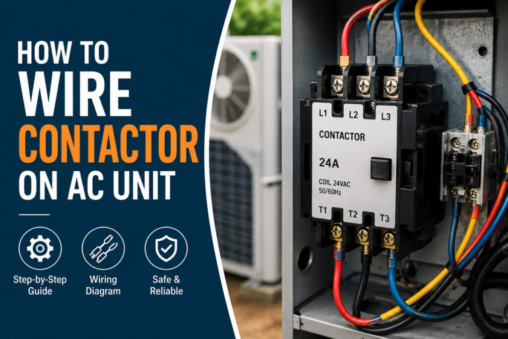
Every residential AC contactor follows the same terminal layout. Understanding what each terminal group does turns the wiring diagram into a readable reference.
Line Terminals — Power In
The input side of the contactor. These connect to the 240V power feed from the disconnect box. L1 receives one leg of the supply; L2 receives the other. These terminals are live whenever the disconnect is closed, regardless of whether the coil is energized.
Load Terminals — Power Out
The output side. T1 connects to the compressor; T2 connects to the condenser fan motor (confirm with the equipment label wiring diagram). When the coil energizes and the contacts close, T1 and T2 become live and power reaches both components.
Coil Terminals — Control Circuit (24V)
Where the 24V thermostat control circuit connects. Not polarity-sensitive on most residential contactors. When the thermostat calls for cooling, 24V energizes the coil, the electromagnet pulls the armature in, and the contacts close — completing the 240V circuit to the compressor and fan.
  ┌─────────────────────────────────┐
  │  240V FROM DISCONNECT (INPUT)   │
  └──────┬──────────────────┬───────┘
         │                  │
    [ L1 ●]              [ L2 ●]     ← LINE TERMINALS (top)
         │   CONTACTOR      │
         │   CONTACTS       │
    [ T1 ●]              [ T2 ●]     ← LOAD TERMINALS (bottom)
         │                  │
  ┌──────┴──────────────────┴───────┐
  │   TO COMPRESSOR & FAN MOTOR     │
  └─────────────────────────────────┘

    [A1 ●]──────────────────[A2 ●]  ← COIL TERMINALS
         24V THERMOSTAT CONTROL         (center / side)
The standard layout: L1 at top-left feeds T1 at bottom-left; L2 at top-right feeds T2 at bottom-right. This is consistent across virtually all residential AC contactors, including single-pole and double-pole designs.
How to Wire a Contactor on an AC Unit — Step by Step
-
Cut power at the disconnect and the breaker panel. Pull the disconnect block next to the condenser, then turn off the AC breaker at the panel. Verify zero voltage at the contactor terminals with a multimeter before touching any wires. The disconnect alone is not sufficient — both must be off and confirmed.
-
Photograph all existing wiring. Before removing a single wire, photograph the old contactor from the front and both sides. Note which wires run to L1, L2, T1, T2, and the coil terminals. This photo is your reinstall reference.
-
Remove wires one at a time and label them. Loosen each terminal screw, pull the wire, and immediately mark it if there’s any uncertainty. Never disconnect all wires first and try to sort them afterward.
-
Mount the new contactor in the same position and orientation as the original — same mounting holes, same terminal positions.
-
Connect L1 and L2 (line terminals). The two wires from the disconnect go to the top terminals — one leg to L1, one to L2. These are the input side.
-
Connect T1 and T2 (load terminals). The compressor and fan wires connect to the bottom terminals. Tighten these terminal screws firmly — a loose connection here causes arcing and premature contact failure.
-
Connect the coil terminals (A1 and A2). The two 24V thermostat control wires connect to the small coil terminals, physically separate from the main line/load block. These are not polarity-sensitive.
-
Verify connections against your reference photo, then restore power at the disconnect and panel. Call for cooling from the thermostat — the contactor should click audibly as the coil energizes and the compressor starts within a few seconds.
Common AC Contactor Wiring Mistakes to Avoid
- Swapping L and T terminals: Connecting the power feed to T1/T2 and the compressor wires to L1/L2 is the most frequent error. The system may start, but the contacts are loaded from the wrong side and wear out much faster than they should.
- Loose terminal screws: Undertightened connections are the most common cause of early contactor failure. The screw must be fully seated against the wire conductor — firm but not stripped.
- Wrong wire gauge on the high-voltage terminals: The L1, L2, T1, and T2 connections must use wire rated for the contactor’s amperage. Undersized wire overheats under sustained load.
- Not verifying zero voltage before beginning: The disconnect cuts power to the cabinet, but the panel breaker must also be confirmed off. Always verify with a multimeter — not by visual inspection of the switch position alone.
When to Call a Licensed HVAC Technician
Contactor replacement is a manageable task with the right preparation. Call a professional if the existing wiring is burned, if wire insulation is damaged along any section of the run, if you can’t confidently identify where each wire belongs, or if the system still doesn’t respond after replacing the contactor. Situations where the fault extends into the compressor terminals, thermostat control board, or the incoming power circuit — including any work that involves changes to the panel-level circuit feeding the condenser — are best handled by a licensed technician.
Frequently Asked Questions
What Are L1, L2, T1, and T2 on an AC Contactor?
L1 and L2 are the line terminals — the input side where 240V power feeds in from the disconnect. T1 and T2 are the load terminals — the output side where power exits to the compressor and condenser fan. L1 feeds T1 through one contact; L2 feeds T2 through the other.
How Do I Wire the 24V Control Circuit on an AC Contactor?
The two thermostat control wires connect to the coil terminals, labeled A1 and A2. These carry 24V. When the thermostat calls for cooling, the signal energizes the coil, the electromagnet closes the contacts, and the compressor starts. The wires are not polarity-sensitive on standard residential contactors.
Can a Single-Pole Contactor Replace a Double-Pole?
No. A double-pole contactor switches both legs of the 240V supply simultaneously. A single-pole only switches one leg, leaving the other leg energized through the compressor at all times — a code violation and a safety hazard. Always replace like-for-like on pole count.
What Happens If the L and T Terminals Are Wired Backwards?
The system may start, but the contacts are loaded from the wrong direction, accelerating pitting and wear. The contactor will fail earlier than it should and may cause heat damage to the terminal block and surrounding wiring.
Is the Wiring the Same for a 30A and 40A Contactor?
The terminal layout and wiring sequence are the same — L1/L2 in, T1/T2 out, coil terminals for the 24V control circuit. The difference is wire gauge: a 40A contactor requires heavier wire on the line and load terminals to handle the higher current safely.
Need Reliable Contactors for Your AC System?
Dvolt manufactures contactors and switching components built to consistent tolerances for residential and commercial HVAC and electrical applications.
Contact Our Team Browse Our ProductsFinal Thoughts
Wiring a contactor on an AC unit comes down to two circuits and four labeled terminals. L1 and L2 bring 240V power in from the disconnect; T1 and T2 carry it out to the compressor and fan. The coil terminals carry 24V from the thermostat and close the switch. Getting those connections right — verified against a reference photo before power is restored — is the complete task.
The air conditioner contactor wiring diagram is simpler than it looks. Once you understand the difference between the line and load terminals and how the control circuit triggers the high-voltage contacts, the wiring itself is the easy part. The safety procedure around it takes more time — and that’s exactly as it should be.