Understanding Contactor Coil Terminals, Wiring Diagrams, and How Contactors Actually Work
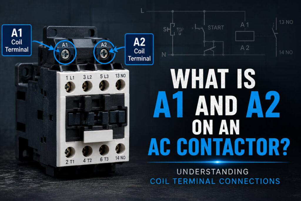
If you’ve opened up an AC contactor and found two terminals marked A1 and A2, you’ve found the coil circuit — the part of the contactor that controls everything else. Understanding what is A1 and A2 on a contactor is the key to reading any contactor wiring diagram, whether it’s for an HVAC system, a lighting contactor, or a three-phase motor starter.
A1 and A2 are standardized terminal labels used across nearly every contactor brand — ABB, Allen-Bradley (AB), Schneider, Square D — because the coil circuit works the same way regardless of manufacturer. Once you understand what happens at A1 and A2, the rest of a contactor wiring diagram becomes much easier to follow.
This guide covers what A1 and A2 actually do, how they fit into a full contactor wiring diagram, common coil voltages like 24V, 120V, and 240V, and how to wire a basic AC contactor correctly and safely.
What Are A1 and A2 on a Contactor?
A1 and A2 are the two terminals on a contactor’s electromagnetic coil. Applying the coil’s rated control voltage across A1 and A2 energizes the electromagnet inside the contactor, pulling the main contacts closed and allowing power to flow through the load side. Remove voltage from A1/A2, and a spring releases the contacts, cutting power to the load.
Why Coil Terminals Are Always Labeled A1/A2
The A1/A2 designation comes from IEC standard terminal marking conventions, which is why the labeling is consistent across contactor diagram symbols regardless of brand. Whether you’re looking at an ABB contactor, an Allen-Bradley (AB) contactor, or a Schneider contactor relay, the coil terminals will almost always be marked A1 and A2.
A1/A2 vs. Load-Side Terminals
A1 and A2 are entirely separate from the load-side terminals, typically labeled L1/L2/L3 on the line side and T1/T2/T3 on the load side for a three-phase contactor, or simply numbered 1-2, 3-4 pairs on a smaller AC contactor. The coil circuit at A1/A2 controls whether current flows through those load terminals — it doesn’t carry the load current itself.
How a Contactor Works
Contactor working is straightforward once you separate the two circuits involved. A low-power control signal energizes the coil at A1/A2, which creates a magnetic field that pulls an armature and the attached main contacts closed. Those main contacts then complete the high-power load circuit, sending full current to whatever the contactor controls — a compressor, a lighting bank, or a motor.
Common Coil Voltages: 24V, 120V, and 240V
A1/A2 coil circuits come in several standard voltages, and matching the coil voltage to your control circuit is essential. A 24V contactor wiring diagram is common in HVAC systems, where a thermostat’s low-voltage output drives the coil. A 120V contactor wiring diagram or 240 volt contactor wiring diagram is more common in lighting contactors and motor control circuits powered directly from line voltage.
Contactor Wiring Diagrams by Application
AC/HVAC Contactor Wiring
A typical wiring diagram for AC contactor units shows a 24V thermostat signal landing on A1/A2, with L1/L2 line voltage feeding the compressor and condenser fan through the main contacts.
Lighting Contactor Wiring
A lighting contactor wiring diagram often uses a switch or timer on the A1/A2 coil circuit to control multiple poles of lighting circuits from one central point.
Three-Phase Contactor Wiring
A three phase contactor wiring diagram shows L1/L2/L3 on the line side and T1/T2/T3 on the load side, with the same A1/A2 coil logic controlling all three poles simultaneously.
Auxiliary Contact Wiring
An auxiliary contactor wiring diagram adds small NO/NC contacts that switch alongside the main contacts — useful for interlocks, indicator lights, or feeding a control signal to an MCB (miniature circuit breaker) or another downstream device.
Types of Contactors
| Contactor Type | Typical Use |
|---|---|
| AC Contactor | HVAC compressors and condenser fans |
| Lighting Contactor | Commercial lighting banks, multi-pole switching |
| Magnetic Motor Contactor | Motor starters, industrial equipment |
| Definite Purpose Contactor | Single-application HVAC and refrigeration loads |
How to Wire a Basic AC Contactor
Tools You’ll Need
- Multimeter – Confirms coil voltage and continuity before energizing
- Insulated Screwdriver – Lands wires on A1/A2 and load terminals
- Wiring Diagram for the Specific Contactor Model – Confirms terminal layout, since numbering can vary slightly by brand
- Voltage Tester – Confirms the circuit is de-energized before working on it
Step 1: Confirm the contactor’s coil voltage matches your control circuit — 24V, 120V, or 240V. Step 2: Land the control circuit’s two wires on A1 and A2; polarity typically doesn’t matter for AC coils. Step 3: Connect line voltage to the L1/L2 (or L1/L2/L3) terminals. Step 4: Connect the load — compressor, lights, or motor — to the corresponding T1/T2 (or T1/T2/T3) terminals. Step 5: Restore power and test that the contactor pulls in when the control circuit is energized.
Common Mistakes to Avoid
- Wiring the load circuit to A1/A2 instead of the coil control circuit
- Using a contactor with the wrong coil voltage for the available control signal
- Confusing auxiliary NO/NC contacts with the main load-carrying contacts
- Assuming every brand numbers load terminals identically without checking the specific wiring diagram for contactor model in hand
- Working on load-side terminals without confirming the circuit is fully de-energized
When to Call a Licensed Electrician
You should contact a professional if:
- You’re wiring a three-phase or motor control contactor rather than a simple single-pole application
- The contactor won’t pull in even after confirming correct coil voltage — see our guide on how to know if your AC contactor is bad
- You’re unsure which terminals are load-side versus coil-side on an unfamiliar model
- The installation involves a permit or inspection requirement in your area
- You notice burned or pitted contacts that suggest a deeper electrical fault, similar to symptoms covered in our guide on diagnosing failed electrical components safely
Frequently Asked Questions
What Is A1 and A2 on a Contactor?
A1 and A2 are the two coil terminals. Applying the rated control voltage across them energizes the contactor’s electromagnet, pulling the main contacts closed to power the load circuit.
Does Polarity Matter on A1 and A2?
For AC coils, no — either wire can go on either terminal. DC coil contactors are typically polarity-sensitive, so always check the nameplate if you’re unsure which type you have.
What’s the Difference Between a Contactor and a Relay?
They work on the same coil-and-contacts principle, but contactors are built for much higher current loads — motors, compressors, lighting banks — while relays handle lighter-duty switching.
What Voltage Should Be on A1 and A2?
Whatever the contactor’s coil is rated for — commonly 24V, 120V, or 240V. Check the nameplate before wiring, since applying the wrong voltage can damage the coil or prevent it from pulling in.
Need a Reliable AC or Lighting Contactor?
Dvolt manufactures AC contactors and magnetic contactors engineered for consistent coil performance and durable main contacts, for HVAC and industrial control applications alike.
Contact Our Team Browse AC ContactorsFinal Thoughts
A1 and A2 are the starting point for reading any contactor wiring diagram — they’re always the coil terminals, always separate from the load circuit, and always the first thing to confirm before wiring or troubleshooting a contactor. Once that piece clicks, diagrams for AC contactors, lighting contactors, and three-phase motor starters all follow the same underlying logic.
Match the coil voltage to your control circuit, keep the load-side wiring separate and de-energized while you work, and check the specific model’s diagram if anything about the terminal layout looks unfamiliar.